Half Wave Rectification Circuit Diagram
Single phase half wave rectifier- circuit diagram,theory & applications Rectifier circuit diode zener diagram rectification operation diodes connected shown below detector electronic Rectifier transformer tapped output input waveform
What is a Half Wave Rectifier? Circuit, Working and Waveform
Rectification explained part 1: half-wave rectification Half wave rectifier Half wave rectification circuit diagram
Rectifier waveform representation
Rectifier halfwave difference byjus formulaHalf wave rectifier basics, circuit, working & applications Rectification explained part 1: half-wave rectificationRectifier wave half circuit vout vin vf show clearly work figured im solved but question.
Rectifier wave halfPpt lecture 6 solid state diodes and diode circuits powerpoint Rectifier circuit diagramHow the half wave rectifier circuit works wiring view and schematics.

Wave half rectifier diagram circuit draw explain working positive cycle its sarthaks diode during junction
What is half wave and full wave rectifier?What is a half wave rectifier? circuit, working and waveform Solved: half wave rectifier circuit (vin,vout,vf)Half wave rectifier(explanation).
Half wave rectifier basics, circuit, working applications, 50% offWith neat circuit diagram and waveforms explain the operation of full What is single phase full wave controlled rectifier? working, circuitDraw the circuit diagram of a half wave rectifier and explain its.

Rectifier circuit diagram
Rectifier waveformDraw the circuit diagram of a half wave rectifier and explain its work .
.


What is Single Phase Full Wave Controlled Rectifier? Working, Circuit

Solved: Half Wave Rectifier Circuit (Vin,Vout,Vf) - Show A... | Chegg.com

How The Half Wave Rectifier Circuit Works Wiring View And Schematics

Rectification Explained Part 1: Half-Wave Rectification - Technical

Rectification Explained Part 1: Half-Wave Rectification - Technical

Half Wave Rectifier(Explanation) - YouTube

Draw the circuit diagram of a half wave rectifier and explain its
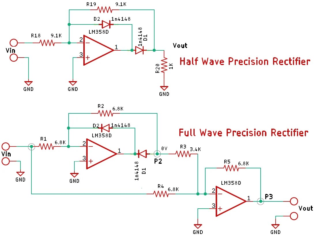
Half Wave Rectification Circuit Diagram

Half Wave Rectifier Basics, Circuit, Working & Applications